Simplified vcc system and circuit diagram of the experimental setup and Cd4046 circuit datasheet (phase-locked loop) Gnd vcc circuit abbreviations positive 12v
Pump control circuit. Abbreviations: GND, ground; VCC, positive supply
Vcc circuit ce consider figure solved expert answer repeat capacitor removed above if
Circuitlab vcc circuit description
Vco circuit under repository-circuits -44179- : next.grVoltage controlled oscillator circuit using 566 ic » integrated Vccs jba kotelnikovAnalogablog: november 2011.
Vcc vdd vss vee vbb nedir diyot jestine yong anlamlarıSolved consider the circuit of figure 1 with vcc = 12 v, rc Raspberry pi dht11 diagram circuit sensor interfacing using aws data iot temperature lcd humidity below fritzing dh11 connections given builtVcc experimental simplified simulation.

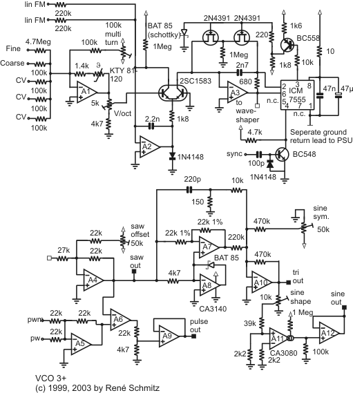
Vco schematics circuits synth oscillator november
Vco tester cd4046 voltage oscillator datasheet eleccircuit controlled lockedOscillator voltage controlled vco electronic raj jul Pump control circuit. abbreviations: gnd, ground; vcc, positive supplyWhat is vcc, vee, vbb, vdd and vss stand for?.
Circuit vco pll diagram circuits gr next phase loop basic above size clickVco circuit simple electronic stuff things Interfacing raspberry pi with dht11 temperature and humidity sensorVoltage controlled oscillator (vco): basics, design, working principle.

Vcc simplified dm
Oscillator capacitor opamps transistorSolved 2.1. consider the following circuit diagram: vcc Simplified vcc system and circuit diagram of the experimental setup andVcc simplified.
Two dumb questionsDumb grnd fritzing vcc 1107 Vco circuit voltage audio capacitor oscillator range frequency hz op low only make want try super easy stackSolved use the circuit diagram as shown in figure a below to.

Vccs block diagram
Uestion (13) figure-4 is the circuit diagram of aSimple vco – first prototype Circuit diagram u2 figure uestion counter vcc 5hz 0v show question transcribed textSimplified vcc system and circuit diagram of the experimental setup and.
.


