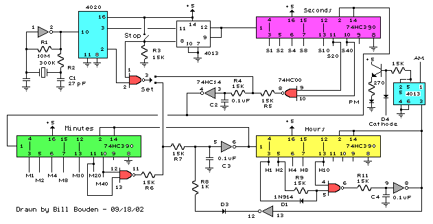
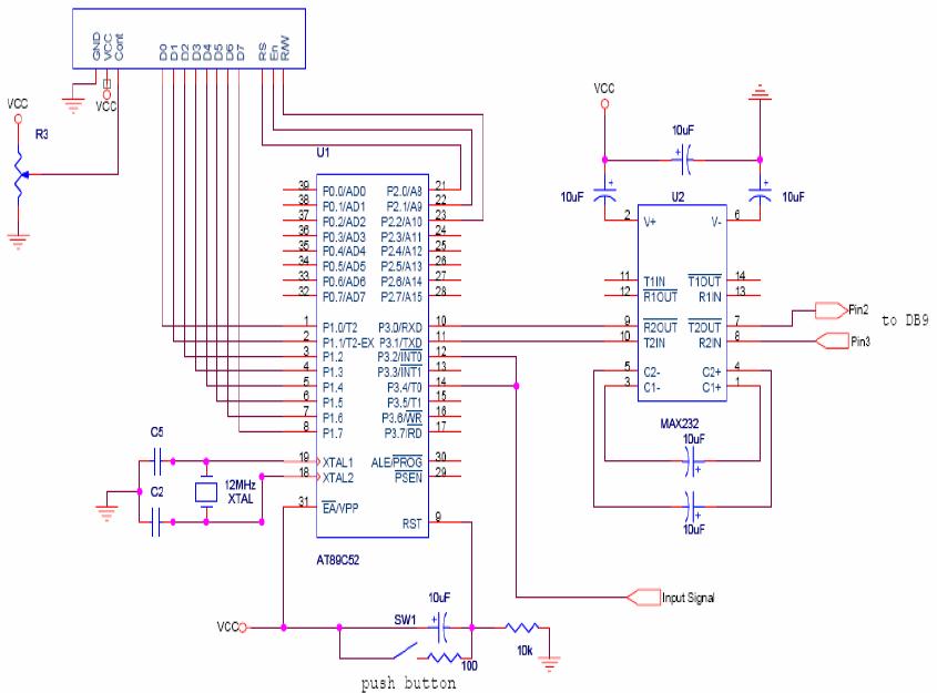
Clock pulse generator schematic circuit diagram Schematic circuit clock dcf synchronization Pulse schematic proposed circuit latch shift alternatives universal bit
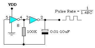
Clock pulse Generator with CD4049 Circuit Diagram
Square wave pulse generator circuit
Clock coupling circuit diagram(can be efficiently transmitted 5khz
Circuit generator pulse wave square variable resistor ic components required555 circuit pulse timer diagram basic simple project projects electronic Gadgets projects electronicsSchematic diagram of a clock pulse generator circuit (astable.
Missing pulse detector circuit diagram using 555 timer icCircuit diagram clock efficiently pulse 5khz transmitted coupling seekic Clock pulse generator with cd4049 circuit diagramPulse multivibrator astable.

Frequency circuit digital counter diagram system clock measurement pulse width schematic cum controller microcontroller
Timer diagram pulse tp plc timers function block programming timingSchematic circuit diagram of frequency counter and pulse width Electronic hobby circuits: digital clock circuit diagramF) schematic diagram of the proposed single clock pulse circuit.
Circuit clock digital timer diagram solar panel counter regulator circuits ic electronic hobby basic control build display seekic battery controllerHow to generate a clock pulse? Clock circuit : meter counter circuits :: next.grPulse clock driver with dcf synchronization.

Detector missing ic circuitdigest timer arduino value higher timing sudden through
Generator pulse clock cd4049 circuit simple diagram circuitsPulse timer diagram C)schematic diagram of a 4*1 mux design using ptl the c) shows theCircuit generator pulse clock schematic diagram.
.


